Digital Audio in the Real World
Read Part One and Part Two
Knowing the theory of digital audio is all well and good, but how do you set all that stuff up on-site? First of all, both good and bad news about digital audio is a lot of the equipment looks after things like sampling and clocking for you. Word clock signal is often carried on the same path as the audio signal, so for a lot of systems, you don’t need to worry about plugging sync cables in separately at all. This automation makes it much more user-friendly and quick to set up, but it also means it can be tricky to troubleshoot because manufacturers will proudly proclaim that their system “just works!” This is also yet another subject where there is no consensus, and each brand has its preferred protocols, cables, and network topology. When using any new equipment, primarily digital, it pays to read the manual: you might find out about some crazy quirks you would never have thought of checking for. You are also likely to have several pieces of equipment from several different manufacturers; follow their advice about how to connect these together, including using the correct convertors or adaptors.
Practise best practice
If you want to avoid digital audio issues, keep your system as simple and neat as you can. Much like analogue, you usually want to minimise the number of connections and cable length between points in your system. For example, connect your devices in a “star” topology when possible – this means each unit gets plugged straight to one central device, like a network router for system communication or master clock generator for synchronisation (like in figure 1a). The alternative is a “daisy chain” topology – linking from one unit to the next (figure 1b). Even if you use a direct output from a device, each loop through introduces latency to your system. It may be a fraction of a millisecond, but if you have several units, those can add up to cause trouble. It can also mean that if one device or cable fails in the chain, everything downstream of that loses connection. If your devices don’t have the ability to link out, you’ll need to use a splitter or ‘T’ connector to carry the chain on, which is another potential point of failure or signal loss. However, certain manufacturers recommend leaving their section of the set up (e.g., a desk and its stage boxes) connected in a chain for syncing purposes. Their argument is if everything is clocked directly to an external master and it fails, everything will fall out of sync. Their equipment was designed to work together, so allowing it all to clock from one of its own units, which in turn is clocked to your system’s master, means that if the master goes offline all that gear will at least be in sync with each other, if not the rest of your system (figure 1c).
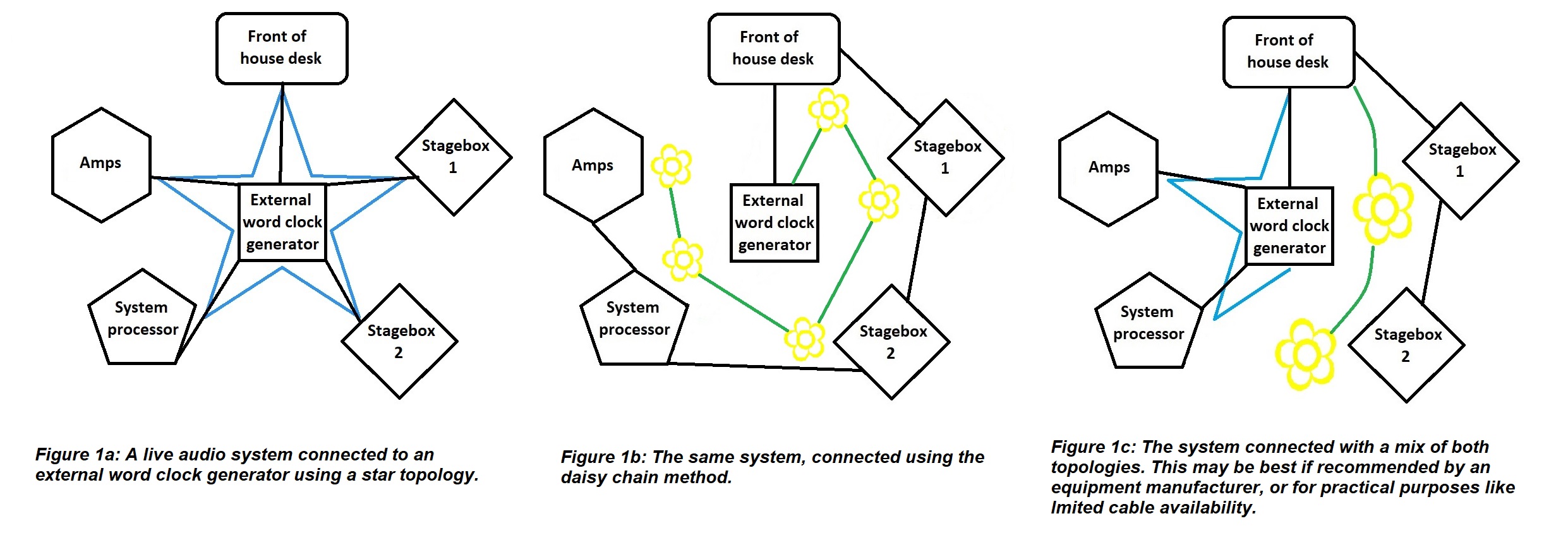
Figure 1: Different methods for connecting a live system
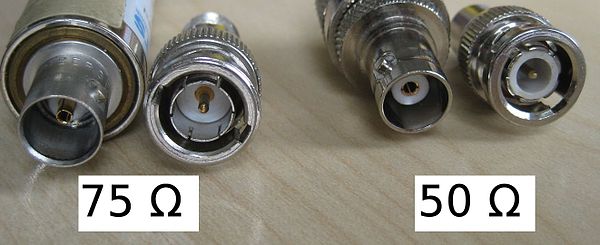
Figure 2: 50 ohm male and female BNC connectors (right) with their dielectric rings clearly visible, and 75 ohm male and female connectors (left) without. Source: By Kaback [CC BY-SA 3.0 (https://creativecommons.org/licenses/by-sa/3.0)], from Wikimedia Commons.
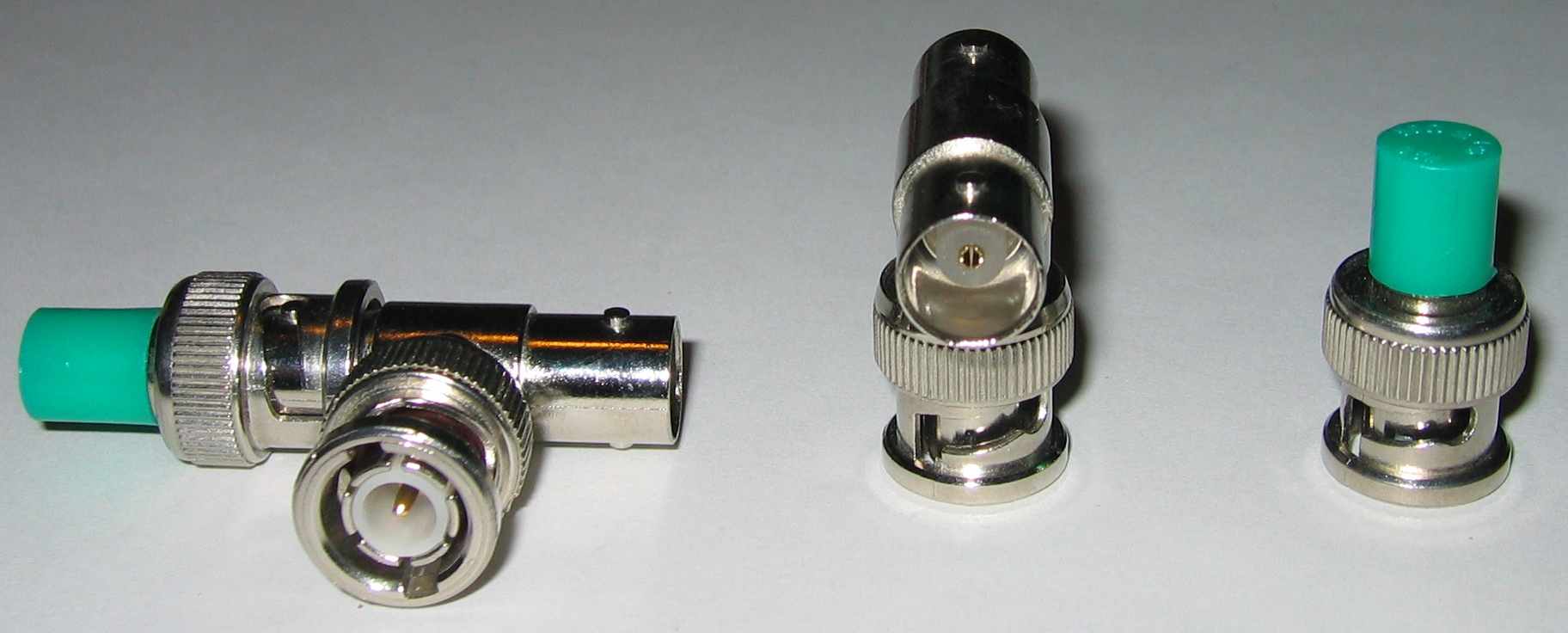
Figure 3: A BNC terminator connected to a T connector (left), a T connector (centre) and a terminator. As you can see by the dielectric material, these are actually 50 ohm connectors and would not be ideal for digital audio setup. Source: By Romantiker [GFDL (http://www.gnu.org/copyleft/fdl.html), from Wikimedia Commons.
Are you using the correct connections?
There are a whole bunch of different cables used to connect digital audio. Confusingly, several have the same connectors as other cables, and look and feel very similar. For example, your device might have BNC sockets, but should you use RG58 coaxial cable or RG59? What’s the difference? RG58 has a characteristic impedance of 50 ohms and is used for RF applications because it can deal with the high power involved in radio transmission. RG59 (you might know it as ‘video cable’) is 75 ohms and is what you need for digital audio connections. Its lower impedance will let the signal pass through it more efficiently and accurately.
Similarly, AES3 cable uses XLR connectors but is 110 ohms rather than mic cable’s 75 ohms. If you’re lucky, the grade will be printed along the length of the cable, but if not, RG59 and AES3-grade cables tend to be stiffer and less flexible than RG58 and mic cable (beware of RG213, which is even thicker than RG59! There are quite a few different cables with BNC and XLR connectors out there. If you are in charge of organising cables in your workplace, please store all these different ones in clearly marked places, far away from each other! It will save a lot of confusion). There are two different BNC connectors: a 50 ohm one with white plastic ‘dielectric’ rings and a 75 ohm one without (see figure 2). However, this isn’t a foolproof way of identifying the cable itself, because some manufacturers or repair people cut corners or are genuinely mistaken and can use the wrong ones. The shorter the distance, the less critical it is to use the correct cable, but if you’re having issues and you know you cheaped out and used let’s say mic cable instead of AES3-grade cable, swapping it for the real deal is a smart move. Make sure you don’t connect cables of different impedances too. Each time you connect a 50 ohm and 75 ohm coax together it can result in the loss of roughly 5% of your signal (this is also something to bear in mind if you know your cables have the wrong impedance connectors).
If you connect your devices to a word clock generator separate to the audio transmission, you also need to make sure that each path is terminated, to stop parts of the signal being reflected back down the cable and causing jitter. Some devices have a switchable internal terminator that you can select, or if you’re using BNC you can plug a T connector into the input of the last device in the chain, with the word clock plugged into one side of the T and a (75 ohm) terminator (see figure 3) on the other side.
Is everything singing from the same hymn sheet?
Once everything is powered up, make sure all your devices are running at the same sample rate. Most equipment these days has an internal sample rate convertor, which can switch between sample rates, called up or downsampling. Downsampling to the slowest device’s rate is the norm in live audio. This option is usually found in the system/settings menu, but sometimes there is a physical switch on the unit. If a device has a second brain/engine or fallback feature, make sure that it is also set to the correct sample rate. Some systems are now smart enough to choose the best word clock to be the master themselves and even switch to the second best one if something happens to the first, without interrupting the audio. If your system doesn’t do this, decide on a master clock and tell each device what it is. Again, this will be in the system/settings menu.
Is the network working?
If you networked units together, make sure they each have a unique IP address, that can be seen by the router (if you have a straightforward setup you may not need a separate router). If two or more devices have the same IP address, or any device has the wrong type of IP address, it will cause issues. Here is a brief rundown of the basics of IP addressing:
Static IP: You set the IP (‘internet protocol’) addresses of each device manually, and they stay the same until you change them. This is best for most live audio cases, so you can keep track of all your devices and can quickly identify which unit is faulty, for example, by its IP address.
DHCP (Dynamic Host Configuration Protocol): You let the router assign addresses. This is faster, and best if other units are likely to be added to the network without your knowledge (this is normally used for things like wifi networks in offices and cafes). As devices come and go, they are certain to have unique IP addresses and won’t clash. However, the same unit can be assigned different IP addresses over time, which can get confusing.
Subnet: The part of the IP address that a router looks at to see all the devices in a particular network. e.g., a desk might be 192.12.34.3, a stagebox might be 192.12.34.4, and they are both part of the “192.12.34.x” subnet. A laptop with the address 168.12.34.5 would not be part of that subnet.
Subnet mask: The number that defines the range of the subnet. For each section of the mask, if the number is 255, each IP address must match at that section exactly. If the number is 0, it can be any value between 0 and 255. For example, if the subnet mask is 255.255.255.0, each device’s address must match in the first three sections. 192.12.34.3 and 192.12.34.4 would be seen, but if an amp was set to 192.12.56.7, it wouldn’t be seen. If you expanded the subnet mask to 255.255.0.0 the amp would then be seen by the router, along with anything else that had an IP address starting with 192.12. (so that laptop would still not be seen as part of the subnet). It is best to avoid assigning IP addresses that end in 0 or 255 because these are often used by the router for its own system tasks.
It might seem like a lot to take in, but most of this only really comes down to setting up like you would an analogue system, then doing a few extra checks in your gear’s settings menus. Getting the fundamentals right will minimise the need for troubleshooting, which I promise I will get on to in my next post!