Never mind the bit clocks… it’s a word clock primer
My last blog dealt with translating audio into a digital signal. The next step is keeping that signal in time when it’s being captured, processed and sent to different parts of the system. This is where the fabled word clock comes in. If anything weird ever happens with a digital set up, like odd clicks or pops over the PA, you can seem wise beyond your years by nodding sagely, saying “Hmm, it sounds like a clocking issue”, then making your excuses and leaving before any further questions can be asked. However, you can become a rare and very valuable member of your audio team by actually learning what word clocks are, how they work and how to fix the most common problems they can cause. They might seem strange and complicated, but they are of course not black magic. It’s all about crystals.
So… what is a word clock?
Any device receiving audio sees a string of 1s and 0s. How does it know whether 0000011100001011 is two samples, reading 00000111 (= 7) and 00001011 (=11), or the second half of a sample, a full sample (01110000 = 112), and the first half of the next one? As you can see, the resulting values can be very different, so it’s essential to get it right to the exact bit.
A word clock is a signal that is sent at a very accurate frequency of one square wave per sample (the bits in each sample make up a ‘word’). This signal is produced by passing an electrical current through a small crystal inside a word clock generator. The rising edge of the resulting wave means 1; the falling edge means 0. The clock runs alongside the audio signal, with 1 usually meaning “this is the start of the sample” and 0 meaning “this is the end.” Different shapes and sizes of crystal resonate at different frequencies, then more subtle changes are controlled by variations in the voltage running through the circuit and temperature. Some clock generators even keep their crystals in tiny ‘ovens’ to keep the temperature constant.
What the clock?
Clocks are necessary for a few different stages in the signal path. AD convertors might take a fixed number of samples per second, but they still need to make sure those samples are evenly spaced. If they aren’t, the waveform will end up deformed when reproduced by something that is in time. Thinking back to the video analogy from the last post, it’s like film taken on old hand-cranked cameras: uneven capturing of the signal leads to weird inconsistencies when it’s played back. In audio, it’s referred to as jitter. This can also happen when an accurately-captured signal gets reconverted with an unreliable clock, like a film being played on a clunky projector (see figure 1). Clocks used to trigger the capturing of the signal are often called sample clocks. There are also bit clocks, which produce one cycle per bit. These days they are only used for signal transport within devices, for example from one PCB to another. You’re very unlikely to encounter a problem with a bit clock, and if you do there isn’t much you can do except send it back for repair. You might also hear people referring to word clock as sync clock, signal clock or simply clock.
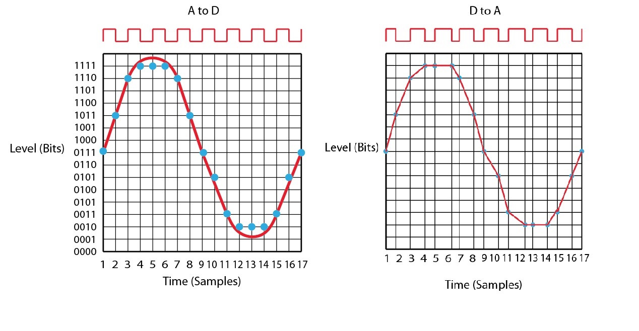
An AD converter with a stable word clock (represented by the square wave at the top) captures an accurate waveform (left), but if it’s converted back to analogue through a DA converter with an unstable clock, the waveform will become deformed (right). Source: Apogee Knowledge Base http://www.apogeedigital.com/knowledgebase/fundamentals-of-digital-audio/what-is-jitter/”
One clock to rule them all
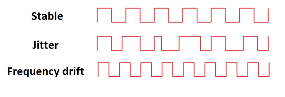
A stable clock compared to a jittery one, compared to one whose frequency has drifted. Jitter is caused by a varying clock frequency, whereas a clock that has drifted has a pretty stable frequency. It’s just the wrong one. Source: Apogee Knowledge Base http://www.apogeedigital.com/knowledgebase/fundamentals-of-digital-audio/word-clock-whats-the-difference-between-jitter-and-frequency-stability/”
What we are really interested in for live audio is using word clock to keep multiple devices, e.g., the front of house desk, monitor desk, and system processors, in sync. Think of it like keeping a band in time: most digital devices on the market have their own internal clock, so it’s like each member of the band having their own click (or metronome if you’re that way inclined). If it’s a solo artist, there’s no problem. Even if the click wanders a bit, it probably won’t be noticeable, because there’s nothing to compare it to. However, when there are several members, they need to stay in tempo. Neither clocks nor clicks are perfect, and even if everyone starts off together, they will eventually fall out of sync (known as frequency drift. See figure 2). It makes sense to choose one person to keep the beat for everyone else, like the drummer. Much in the same way, you need to designate one device in your system to be the master clock, and the other devices are slaves who sync their clocks to the master. Sometimes, it can be even better to get a separate device whose only job is to keep time, i.e., an external word clock generator. This is like hiring a professional conductor for the band. Much like a conductor though, they can be very expensive and for the most part aren’t necessary as long as you have a good enough band/set up.
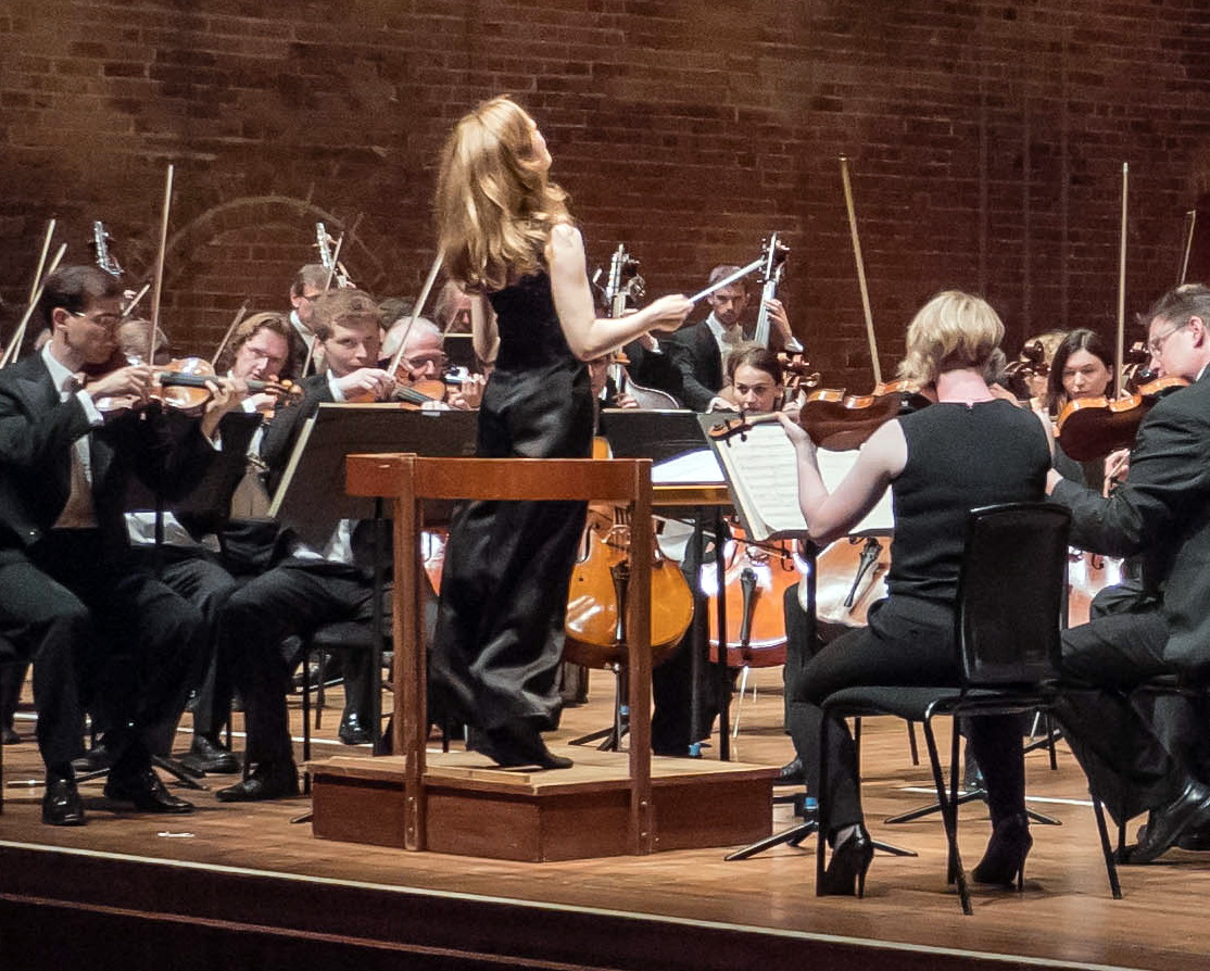
“Mirga Gražinytė-Tyla conducting the City of Birmingham Symphony Orchestra at the Snape Maltings Concert Hall during the Aldeburgh Festival, 2017, by Matt Jolly. https://en.m.wikipedia.org/wiki/File:Mirga_Gra-inyt–Tyla_conducts_the_CBSO,_Aldeburgh_Voices_and_Aldeburgh_Music_Club_at_Aldeburgh_Festival-crop.jpg”
Each device still uses its own clock when following the master. They constantly monitor at what phase in the cycle the incoming clock signal is and compare it to their own. If the two fall out of time, the device can adjust its clock (usually by varying the voltage running through the crystal) until it’s locked in sync. The circuit that does this is called a phase-locked-loop. It’s like a band member nudging the speed of their click or metronome until it matches the conductor. However, some common sense is needed. You don’t want to constantly adjust for every tiny discrepancy, nor do you want everyone to follow when the conductor is obviously wrong, like if he sneezes or falls over. A phase-locked loop’s sensitivity can be adjusted, so it ignores fleeting differences and remains locked to the last signal it received if the master clock outputs major errors or drops out of the system. The device will then continue at that speed until the master gets reinstated or replaced, but will slowly drift if this doesn’t happen. The sensitivity can also be adjusted depending on how good the device is compared to the master. If your conductor isn’t the best, it might be better to listen to your own click when in doubt (or invest in a better conductor). In the next post, I’ll discuss how all this relates to our real life setups.