DFTs, FFTs, IFTs…Oh My!
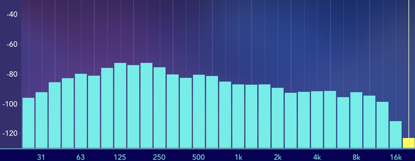
The real-time analyzer (RTA) has long been a familiar tool in the audio engineer’s arsenal. Often the RTA is seen in the wild set up as a measurement microphone into an audio interface. This way the engineer can look at the frequency response of the signal received by the measurement mic. A long-time favorite application among engineers of the RTA has been for identifying frequency values for audible problems like feedback. Yet the albatross of the RTA is that it measures a single input signal with no comparison of input versus output. As one of my mentors Jamie Anderson used to say, the RTA is the “system that best correlates to our hearing”.
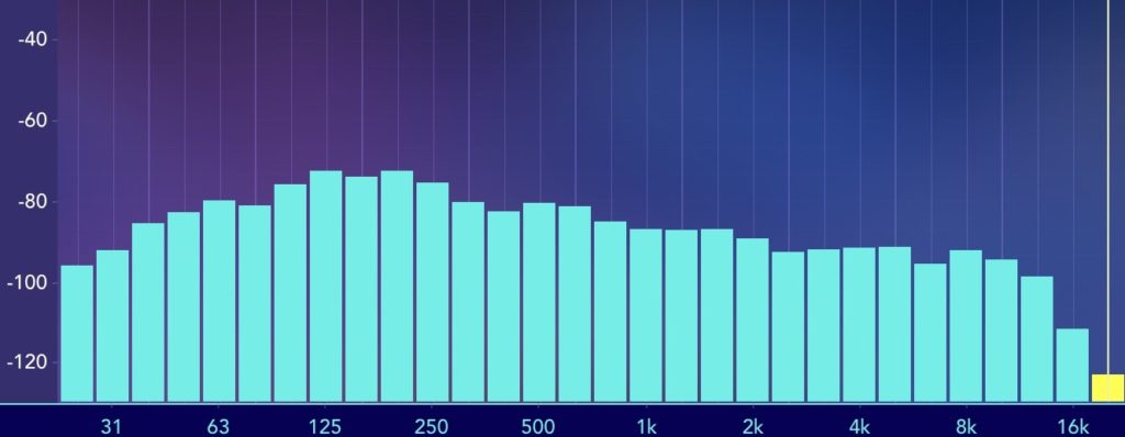
You can find a RTA in many platforms from mobile apps (Such as this screenshot from the Spectrum app) to car stereos to measurement analysis software
In one aspect, the RTA mic acts like your ears taking the input signal and displaying the frequency response. It can be viewed over a logarithmic scale similar to how we, as humans, perceive sound and loudness logarithmically. Yet even this analogy is a bit misleading because, without us realizing it, our ears themselves do a bit of signal processing by comparing what we hear to some reference in our memory. Does this kick drum sound like what we remember a kick drum to sound like? Our brain performs transfer functions with the input from our ears to tell us subjective information about what is happening in the world around us. It is through this “analog” signal processing that we process data collected from our hearing. Similarly, the RTA may seem to tell us visually about what we may be hearing, but it doesn’t tell us what the system is actually doing compared to what we put in it. This is where the value of the transfer function comes into play.
The Transfer Function and The Fourier Transform:
Standing at FOH in front of a loudspeaker system, you play your virtual soundcheck or favorite playback music and notice that there seems to be a change in the tonality of a certain frequency range that was not present in the original source. There could be any number of reasons why this change has occurred anywhere in the signal chain: from the computer/device playing back the content to the loudspeaker transducers reproducing it. With a single-channel analysis tool such as an RTA, one can see what is happening in the response, but not why. For example, the RTA can tell us there is a bump of +6dB at 250Hz, but just that it exists. When we take the output of a system and compare it with reference to the input of a system, then we are taking what is called a transfer function of what is happening inside that system from input to output.
A transfer function allows for comparison of what is happening inside the system
The term “transfer function” often comes up in live sound when talking about comparing a loudspeaker system’s output with data gathered from a measurement mic versus the input signal into a processor (or output of a console, or other points picked in the signal chain). Yet a “transfer function” refers to the ratio between output and input. In fact, we can take a transfer function of all kinds of systems. For example, we can measure two electrical signals of a circuit and look at the output compared to the input. The secret to understanding how transfer functions help us in live sound lies in understanding Fourier transforms.
In my blog on Acoustics, I talked about how in 1807 [1], Jean-Baptiste Fourier published his discovery that complex waveforms can be broken down into their many component sine waves. Conversely, these sine waves can be combined back together to form the original complex waveform. These component sine and cosine waves comprise what is known as a Fourier series (recognize the name?). A Fourier series is a mathematical series that is composed of sine and cosine functions, as well as coefficients, that when added to infinity will replicate the original complex waveform. It’s not magic, it’s just advanced mathematics! If you really want to know the exact math behind this, check out Brilliant.org’s blog here [2]. In fact, the Fourier series was originally discovered in relation to describing the behavior of heat and thermal dynamics, not sound!
A Fourier series defines a periodic function, so one would think that since any complex wave can be broken down into its component sine and cosine waveforms over a defined period of time, then one should be able to write a Fourier series for any complex waveform…right? Well, as contributors Matt DeCross, Steve The Philosophist, and Jimin Khim point out in the Brilliant.org blog, “For arbitrary functions over the entire real line which are not necessarily periodic, no Fourier series will be everywhere convergent” [2]. This essentially means that for non-periodic functions, the Fourier series won’t always come down to a periodic, or same recurring, value. Basically, this can be extrapolated to apply to the most complex waveforms in music. The Fourier transform helps us analyze these complex waveforms.
In a PhysicsWorld video interview with Professor Carola-Bibiane Schönlieb of the University of Cambridge in the UK, she describes how the Fourier transform is a mathematical process (think multiple steps of mathematical equations here) that takes functions in the time domain and “transforms” them into the frequency domain. The important part here is that she notes how the transform function “encodes how much of every frequency, so how much of each sinusoid, of a particular frequency is present in the signal” [3]. Let’s go back to the intro of this section where we imagined sitting at FOH listening to playback and hearing a difference between the original content and the reproduced content. Conceptually, by using Fourier transforms of the output of the PA versus the input signal, one can compare how much of each frequency is in the output signal compared to the input! Before we get too excited, there are a couple of things we have to be clear about here.
Let’s take a few conceptual steps back and briefly discuss what we really mean when we talk about “analog” versus “digital” signals. Without going into an entire blog on the topic, we can find some resolve by defining an analog signal as a continuous range of values in time, whereas digital signal processing takes discrete values of a signal sampled over some interval of time [4]. In order for us to make use of a Fourier transform in the world of digital signal processing and to transform discrete values into the frequency domain, there must be discrete values in the time domain. This seems like a rhetorical statement, but the point here is that ideally, we want our system to behave linearly so that the sum of the outputs is the same as the sum of the inputs, or rather there is some proportionality to the behavior of the output versus the input. Non-linear behavior leads to things like intermodulation distortion, which may or may not be desired in your system. It also leads to inaccurate correlations between data. In systems with linear characteristics on the output versus input in the time domain, we can perform processing with predictable, calculable responses in the frequency domain.
The DFT and The IFT
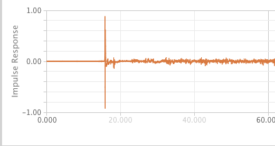
In Understanding Digital Signal Processing, Richard G. Lyons unveils that with linear time-invariant systems (so systems where the same time offset exists on the output as the input), if we know the unit impulse response (IR), we can also know the frequency response of the system using a discrete Fourier transform (DFT). Lyons defines the impulse response as “the system’s time-domain output sequence when the input is a single unity-valued sample (unit impulse) preceded and followed by zero-valued samples […]” [5]. To make a loose analogy to terms in acoustics, we can think of an impulse signal as a gunshot fired in an empty room: there is the initial amplitude of signal followed by the decay or reverberant trail of the signal heard in the room. You can imagine a unit impulse response as a version of that gunshot with no decay or reverberance and just the initial impulse, or a value like a one (as opposed to zero) over a sample of time. Lyons unveils that if we know the “unit impulse response” of the system, we can determine “the system’s output sequence for any input sequence because the output is equal to the convolution of the input sequence and the system’s impulse response […] we can find the system’s frequency response by taking the Fourier transform in the form of a discrete Fourier transform of that impulse response” [6]. If you have used a convolution reverb, you are already familiar with a similar process. The convolution reverb takes an impulse response from a beautiful cathedral or concert hall and convolves it with the input signal to create an output signal that “combines” the frequency response of the IR with the input signal. We can determine the frequency response of the system through a DFT of the impulse response, and it works both ways. By performing an inverse Fourier transform, we can take the frequency domain data and return it to the time domain and deconvolve the impulse response. The impulse response becomes the key to it all!
Example of an impulse response from data captured and viewed in L-Acoustics M1 software
Back when computers were less efficient, it took a lot of time to crunch these numbers for the DFT, and thus the Fast Fourier Transform (FFT) was developed to run numbers through the Fourier transform quicker. Basically, the FFT is a different algorithm (the most popular being the radix-2 FFT algorithm) that reduces the number of data points that need to be calculated [7]. Even though FFTs are still the most popular form of Fourier transform, the development of more efficient and more affordable computers allows us to crunch numbers much faster so this need for extra efficiency is less important than it used to be.
An important concept to also remember when discussing FFTs is that we are talking about digital audio and so the relationship between time and frequency becomes important in regards to frequency resolution. In my last blog “It’s Not Just a Phase,” I talk about the inverse relationship between frequency and the period of a wave. Longer wavelengths at lower frequencies take a longer period of time to complete one cycle, whereas higher frequencies with shorter wavelengths have shorter periods in time. Paul D. Henderson points out in his article, “The Fundamentals of FFT-Based Audio Measurements in SmaartLive®” that in a perfect world, one would need an infinite amount of time to reproduce the entire complex signal from a Fourier series, but this is not practical for real-world applications. Instead, we use windowing in digital signal processing to take a chunk of sampled data over a given time (called the time constant) to determine the time record of the FFT size [8]. Much like the inverse relationship between frequency and the period of a wave, the relationship between frequency resolution of the FFT is inversely proportional to the time constant. What this means is that a longer time constant results in an increase in frequency resolution, and thus lower frequencies require greater time constants. Higher frequencies require smaller time constants to get the same frequency resolution.
The first thing one may think is that longer time constants are the best way to optimize a measurement. In the days where computers were less efficient, running large FFT sizes for greater frequency resolution in low frequencies required a lot of number crunching and processing. This isn’t a problem with modern computers, but it’s also not a very efficient use of computing power. Some programs such as SMAARTv8 from Rational Acoustics offer the option to use multi-time window FFT sizes in order to optimize the time constants to provide adequate frequency resolution for different bandwidths in the frequency spectrum. For example, using a longer time constant and larger FFT size in the lower frequency range and a shorter time constant and smaller FFT size for higher frequency bandpasses.
The Importance Of The Dual-channel FFT
Now that we have a little background on what a Fourier transform is and how we got to the FFT, we can return to the topic of the transfer function mentioned earlier to discover how we can apply all this to help our situation in the FOH example earlier in this blog. With an FFT of a single source signal, we can take our impulse response and the input sequence in the time domain and convolve them to evaluate the response in the frequency domain. Let’s stop here for a second and notice that something sounds familiar. This is in fact how we can get a spectrum measurement of a single channel measurement such as that viewed in an RTA! We can see how much of each frequency is present in the original waveform, just as Carola-Bibiane Schönlieb pointed out. But what do we do if we want to see the transfer function between two signals such as the output of the PA and the input that we are feeding it? This is where we take the FFT one step further by utilizing dual-channel FFT measurements to compare the two signals and view the magnitude and phase response between them.
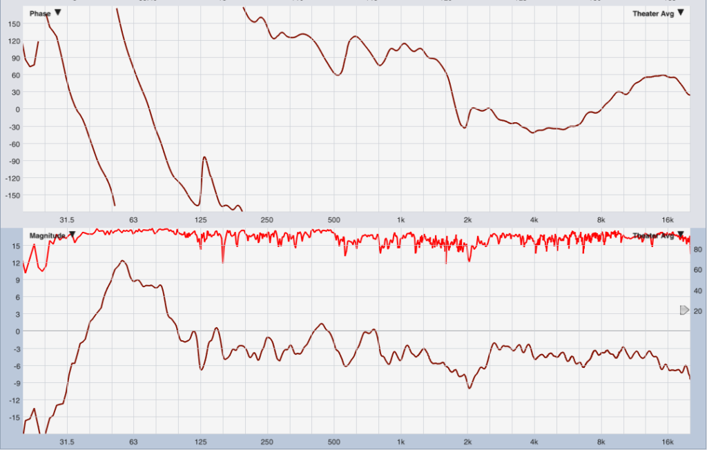
We can take the transfer function of our FOH example with the “output” of our system being the data gathered by measurement mic, and the “input” being the output of our console (or processor or wherever you decide to pick as the point in your signal chain). We then take a FFT of these two signals with the input being the reference and can plot out the difference in amplitude of the frequencies for different sinusoids as the magnitude response. We can also plot the offset in time between the two signals in terms of relative phase as the phase response. For more information on understanding what phase actually means, check out my last blog on phase. Many software programs utilize dual-channel FFTs to run transfer functions and show these plots so that the operator can interpret data about the system. Some examples of these programs are SMAART by Rational Acoustics, M1 by L-Acoustics, the now discontinued SIM3 by Meyer Sound, SysTune by AFMG, among others.
Phase (top) and magnitude (bottom) response of a loudspeaker system compared to the reference signal viewed in Rational Acoustics SMAARTv8 software
The basis of all these programs relies on the use of transfer functions to display this data. The value of these programs in aiding the engineer to troubleshoot problems in a system comes down to asking oneself what are you trying to achieve. What question are you asking of the system?
So The Question Is: What Are You Asking?
The reality of the situation is that, especially in the world of audio, and particularly in music, there is rarely a “right” or “wrong” answer. There are better solutions to solve the problem, but I would venture to say that most folks who have been on a job site or sat in the “hot seat” at a gig would argue that the answer to a problem is the one that gets the job done at the end of the day without anyone dying or getting hurt. Instead of trying to frame the discussion of the RTA versus the dual-channel FFT as a “right” or “wrong” means to an end, I want to invite the reader to ask themselves when they are troubleshooting, “What is the question I am asking? What am I trying to achieve?”. This is a point of view I learned from Jamie Anderson. If the question you are asking is “What is the frequency that correlates to what I’m hearing?” For example, in a feedback scenario, maybe the RTA is the right tool for the job. If the question is, “What is different about the output of this system versus what I put into it?” Then tools utilizing dual-channel FFTs tell you that information by comparing those signals in order to answer the question. There is no “right” or “wrong” answer, but some tools are better at answering certain questions and other tools are better at answering other questions. The beauty of the technical aspects of the audio engineering industry is that you get the opportunity to marry the creative parts of your mind with your technical knowledge and tools at your disposal. At the end of the day, all these tools are there to help you in the effort to create an experience for the audience and to realize the artists’ vision.
References:
[1] https://www.aps.org/publications/apsnews/201003/physicshistory.cfm
[2] https://brilliant.org/wiki/fourier-series/
[3] https://physicsworld.com/a/what-is-a-fourier-transform/
[4] (pg. 2) Lyons, R.G. (2011). Understanding Digital Signal Processing. 3rd ed. Prentice-Hall: Pearson Education
[5] (pg. 19) Lyons, R.G. (2011). Understanding Digital Signal Processing. 3rd ed. Prentice-Hall: Pearson Education
[6] (pg. 19) Lyons, R.G. (2011). Understanding Digital Signal Processing. 3rd ed. Prentice-Hall: Pearson Education
[7] (pg. 136) Lyons, R.G. (2011). Understanding Digital Signal Processing. 3rd ed. Prentice-Hall: Pearson Education
[8] (pg. 2) Henderson, P. (n.d.). The Fundamentals of FFT-Based Audio Measurements in SmaartLive®.
Resources:
American Physical Society. (2010, March). This Month in Physics History March 21, 1768: Birth of Jean-Baptiste Joseph Fourier. APS News. https://www.aps.org/publications/apsnews/201003/physicshistory.cfm
Cheever, E. (n.d.) Introduction to the Fourier Transform. Swarthmore College. https://lpsa.swarthmore.edu/Fourier/Xforms/FXformIntro.html
Brilliant.org. (n.d.) Fourier Series. https://brilliant.org/wiki/fourier-series/
Hardesty, L. (2012). The faster-than-fast Fourier transform. MIT News. https://news.mit.edu/2012/faster-fourier-transforms-0118
Henderson, P. (n.d.). The Fundamentals of FFT-Based Audio Measurements in SmaartLive®.
Lyons, R.G. (2011). Understanding Digital Signal Processing. 3rd ed. Prentice-Hall: Pearson Education.
PhysicsWorld. (2014) What is a Fourier transform? [Video]. https://physicsworld.com/a/what-is-a-fourier-transform/
Schönlieb, C. (n.d.). Carola-Bibiane Schönlieb. http://www.damtp.cam.ac.uk/user/cbs31/Home.html
Also check out the training available from the folks at Rational Acoustics! www.rationalacoustics.com


