Basic Networking For Live Sound Engineers
Part One: Defining A Network
The World of Audio Over IP
There is a certain sense of security that comes from physically plugging a cable made of copper from one device to another. On some level my engineer brain finds comfort believing that, “As long as I patch this end to that end correctly and the integrity of the cable itself has not been compromised, the signal will get from Point A to Point B.” I believe one of the most daunting aspects of understanding networked audio, and audio-over-IP in general, stems from the feeling of self-induced, psychological uncertainty in one’s ability to “physically” route one thing to another. I mean, after all these years consoles still have faders, buttons, and knobs because people enjoy the tactile feedback of performing a move related to their task in audio.
The psychological hurdle that must be overcome is that a network can be much like a copper multicore snake, sending multiple signals all over the place. The beauty and power of it is that it has so much more adaptability than our old copper friend. We can send larger quantities of high-quality signal around the world: a task that would be financially and physically impractical for a single project using physical wires. In this first blog, part 1 of a 3 part series, I will attempt to overview a basic understanding of what a network is and how we can create and connect to a network.
What Is A Network?
A network can refer to any group of things that interconnect to transfer data: think of a “social network” where a group of individuals exchange ideas in person or over the Internet. Cisco Systems (one of the biggest juggernauts of the industrial networking world) defines a network as “two or more connected computers that can share resources such as data, a printer, and Internet connection, applications, or a combination of these resources” (Cisco, 2006 [1]). We commonly see networks created using wired systems, Wi-Fi, or a combination of these. Wired systems build a network using physical Ethernet connections (Cat5e/Cat6 cabling) or fiber, while Wi-Fi uses radio frequencies to carry signals from device to device. “Wi-Fi” is a marketing term for the technology that the Institute of Electrical and Electronics Engineers (IEEE) define in standards 802.11, and we could dedicate an entire blog just to discussing this topic [2].
Unicast vs. Multicast
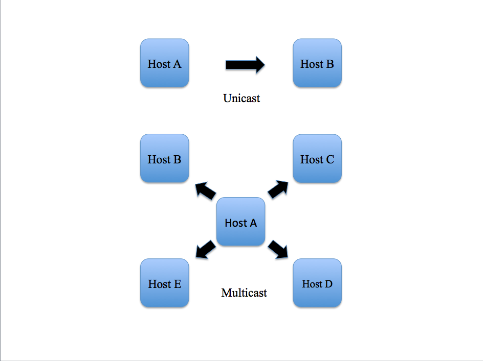
In a given network using the TCP/IP protocol, which stands for “Transmission Control Protocol/Internet Protocol”, devices exchange packets of data by requesting and responding to messages sent to one another. In a unicast message, one device talks directly to another as a point-to-point transmission. In a multicast message, one device can broadcast a message to multiple devices at once. To understand how devices exchange messages to one another, we must understand how IP and MAC addresses work.
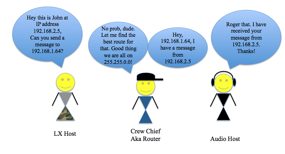
I like to think of a data network like a department in a tour: there are the audio, lighting, video, and other departments, and each department has its own participants who communicate with each other within their own department. Let’s look at the analogy of a network compared to the audio department. Each individual, (the monitor engineer, PA techs, systems engineer, FOH Engineer, etc.), act as discrete hosts performing tasks like a computer or amplifier talking to one another on a data network. Every device has a unique MAC address, which stands for “Media Access Control” Address and, like the name of each person on a crew (except 48-bit and written in hexadecimal [3]), is unique to the hardware of a device on a network. An IP address is a 32-bit number written as 4 octets (if translated into binary) and is specific to devices within the same network [4]. Think of an IP address as different from a MAC address like a nickname is to a given name. There may be several folks nicknamed “Jay” on a crew, maybe Jennifer in Audio and John in Lighting, but as long as “Jay” is talking to people locally in the same department, the other hosts will know who “Jay” is being referred to.

These two networks (or tour departments) are not local to the same network
MAC addresses are specific to hardware, but IP addresses can be “reused” as long as there are no conflicts with another device of the same address within the same local network. A group of devices in the same IP range is called a LAN or Local Area Network. LANs can vary from basic to complex networks and are seen everywhere from the Wi-Fi network in our homes to a network of in-ear monitor transmitters and wireless microphone receivers connected to a laptop. So how do these devices talk to each other within a LAN?
IP Addresses and Subnet Masks within a LAN:
Let’s create a simple LAN of a laptop and a network-capable wireless microphone receiver and dive deep into understanding what composes an IP address. The computer has an IP address that is associated with it via its MAC address and the same goes for the receiver. In Figure A the two devices are directly connected from the network adapter of one to the other with an Ethernet Cat 6 cable.
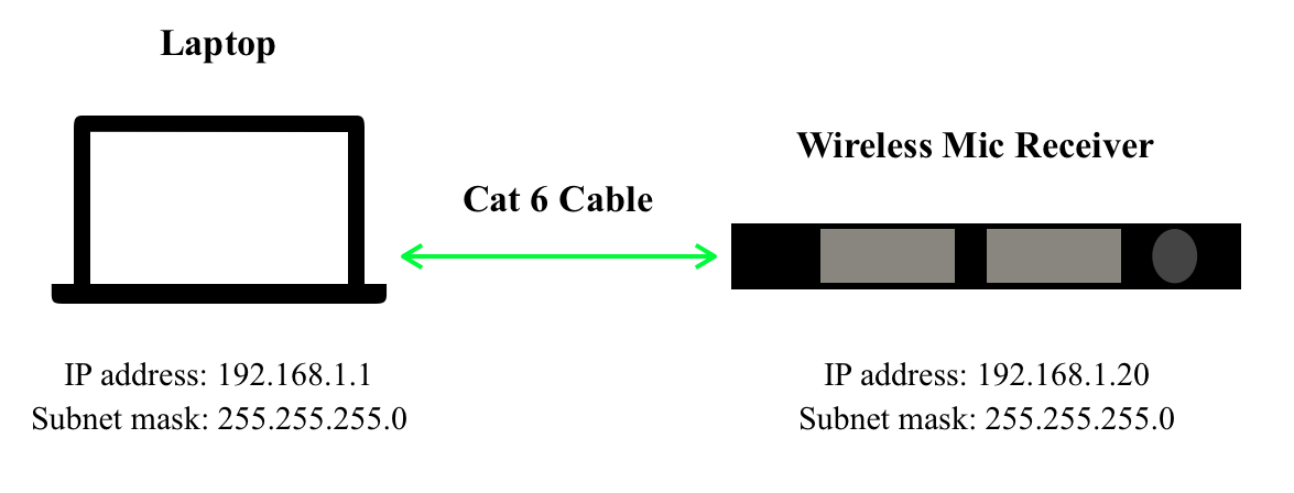
Figure A
The IP address of the laptop is 192.168.1.1 and the IP address of the receiver is 192.168.1.20. Each of the four numbers separated by a period actually translates to an octet (8 bits) of binary. This is important because both devices are on the same subnet 192.168.1.XXX. A subnet is a way of dividing a network by having devices only look at other devices that are within their same network as defined by their subnet mask. There are 254 addresses available on the subnet mask 255.255.255.0. According to a Microsoft article, “Understanding TCP/IP addressing and subnetting basics”, XXX.XXX.XXX.0 is used to specify a network “without specifying a host” and XXX.XXX.XXX.255 is used to “broadcast a message to every host on the network” [5]. So, in this network example, neither the computer nor the receiver can use the IP addresses 192.168.1.0 or 192.168.1.255 because those addresses are reserved for the network and for broadcast. But how does the computer know to look for the receiver in the 192.168.1.XXX IP address range? Why doesn’t it look at 10.0.0.20? This has to do with the subnet mask of each device.
Let me give you a little history about these numbers: believe it or not, but there is an organization whose main gig is to assign IP addresses in the public Internet. The Internet Assigned Numbers Authority (IANA) manages IP addresses that connect you and your Internet Service provider (ISP) to the World Wide Web. In order to prevent conflicts with the IP addresses that connect with the Internet, the IANA enforces a set of standards created by the IETF (Internet Engineering Task Force). One set of standards referred to as RFC 1918 [6] reserves a specific set of IP ranges for private networks, like the example 192.168.1.XXX. That means that anyone can use them within their own LAN, as long as it does not connect to the Internet. To understand more about how our computers connect to the Internet, we have to talk about DNS and gateways, which is beyond the scope of this blog. The key for our laptop and receiver to determine whether another device is local to their LAN lies in the subnet mask. Both devices in Figure A have a subnet mask of 255.255.255.0. Each set of numbers, like the IP address, corresponds to an octet of binary. The difference is that instead of indicating a specific number, it indicates the number of available values for addresses in that range. The subnet mask becomes a lot easier to understand once you think about it in its true binary form. But trust me, once you understand what a subnet mask ACTUALLY refers to in binary, you will better understand how it refers to available IP addresses in the subnet.
A subnet mask is composed of 4 octets in binary. If we filled every bit in each octet except for the last and translated it to its true binary form we would get a subnet mask that looks like this:
255.255.255.0 can also be written as 11111111.11111111.11111111.00000000
Binary is base two and reflects an “on” or “off” value, which means that each position of each bit in the octet, whether it is zero or one, can mathematically equal 2^n (2 to the nth power) until you get to the 8th position.
The octet XXXXXXXX (value X in octet of either 1 or 0) can also be written as:
(2^7)+(2^6)+(2^5)+(2^4)+(2^3)+(2^2)+(2^1)+(2^0)
Binary math is simply done by “filling in” the position of the bit in the octet with a “true” value and then calculating the math from there. In other words, a binary octet of 11000000 (underlines added for emphasis) can be interpreted as
(2^7)+(2^6)+(0^5)+(0^4)+(0^3)+(0^2)+(0^1)+(0^0)=192
OK, OK, roll with me here. So if we do the binary math for all values in the octet being “true” or 1 then in the previous example,
11111111=(2^7)+(2^6)+(2^5)+(2^4)+(2^3)+(2^2)+(2^1)+(2^0)=255
So if we refer back to the first subnet mask example, we can discern based on the binary math that:
11111111.11111111.11111111.00000000=255.255.255.0
When a value is “true” or 1 in a bit in an octet, that position has been “filled” and no other values can be placed there. Think of each octet like a highway: each highway has 8 lanes that can fit up to 254 cars/hosts total on the highway (remember it is base 2 math and the values of 0 and 255 are accounted for). A value of 1 means that the lane has been filled by 2^n cars/hosts where n=lane position on the highway and the lanes count starting at 0 (because it is a computer). So to add another car, it must move to the next lane to the left or bit position. For example, if you climb up from 00000011 to 00000111 each 1 acts like cars filling up a lane, and if the lane is filled, the next bit moves on to the next left lane.
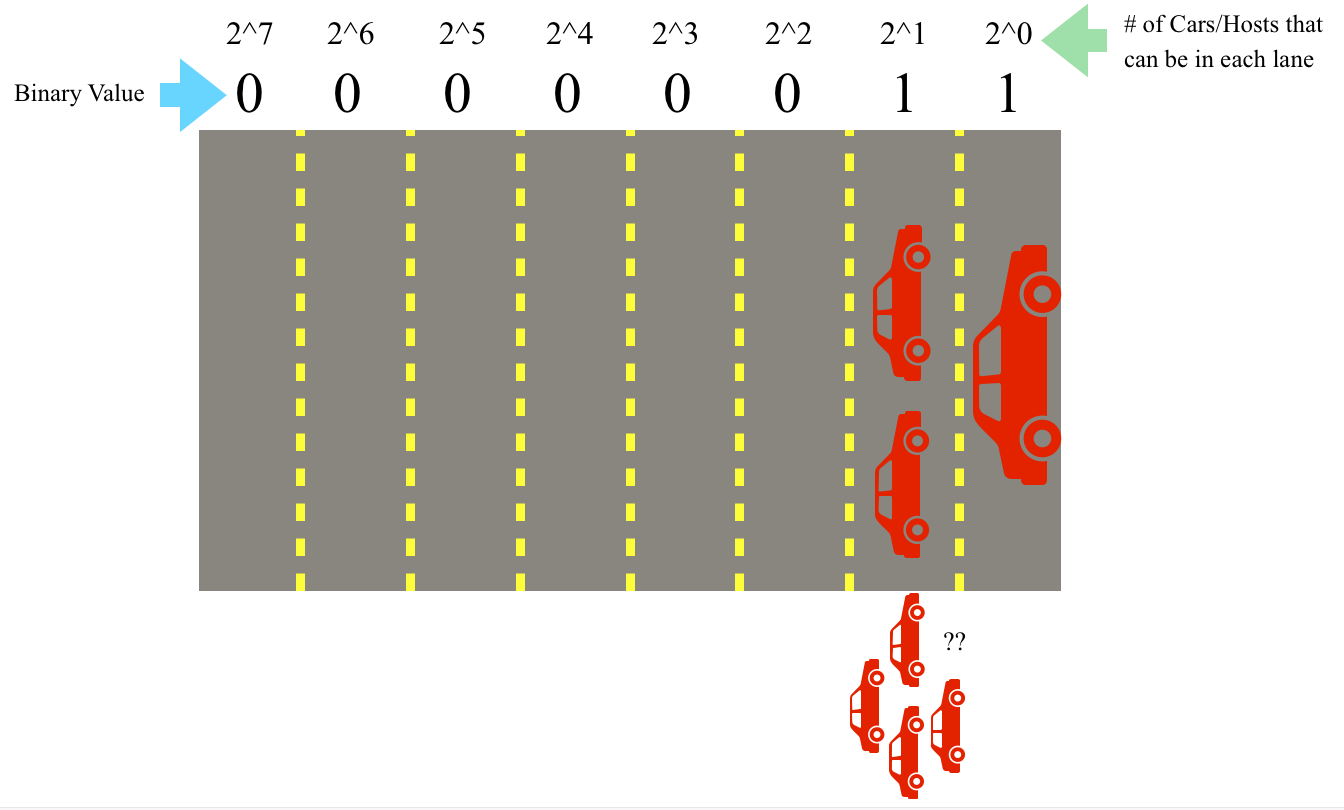
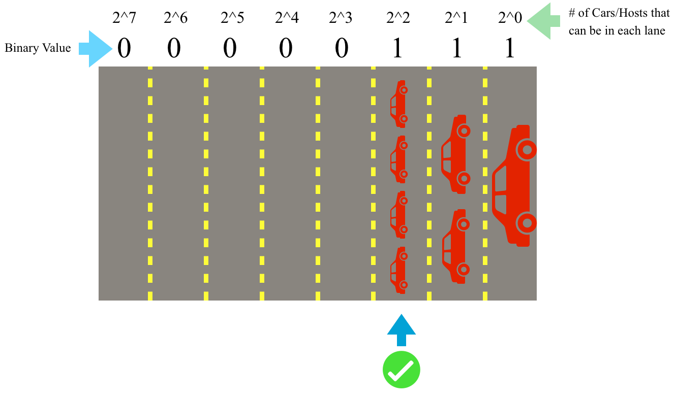
Each position of a bit is like a lane on a highway (top), when the value of the lowest bit is “filled” or True (remember this is an analogy, really it’s either binary On or Off), the ascending value “spills” over to the next bit (bottom)
So why do we care about this? Well if a device has a subnet mask of 255.255.255.0 or 11111111.11111111.11111111.00000000 that means that all the binary values of the first 3 octets must match with the other devices in order for them to be considered to be “local” to the same local network. The only values or lanes “available” for hosts are in the last octet (hence the zeroes). So going back to Figure A our computer and wireless network both have a subnet mask of 255.255.255.0 which indicates that the first 3 octets of the IP address on both devices MUST be the same on both devices for them to talk to each other AND there are only 254 available IP addresses for hosts on the network (192.168.1-254). Indeed both the laptop and receiver are local because they both are on the 192.168.1.XXX subnet, and the subnet mask 255.255.255.0 only “allows” them to talk to devices within that local network.
In this example, we talked about devices given static IP addresses as opposed to addresses created using DHCP. In a static IP address, the user or network administrator defines the IP address for the device whereas a device set to DHCP, or Dynamic Host Configuration Protocol, looks to the network to determine what is the current available address for the device and assigns it to that device on a lease basis [7]. In the world of audio, the type of network addressing you choose for your system may vary from application to application, but static IP addressing is commonly preferred due to the ability for the operator to specify the exact range they want the devices to operate in as opposed to leaving it up to the network to decide. Returning to our earlier analogy of the audio department on a tour, each host needs a way to communicate with one another and also to other departments. What if the PA tech needs to talk to someone in the outside network of the lighting department? This is where routers and switches come into play.
A switch and a router often get referred to interchangeably when in fact they perform two different functions. A switch is a device that allows for data packets to be sent between devices on the same network. Switches have tables of MAC addresses on the same local network that they use to reference when sending data packets between devices. A router works by identifying IP addresses of different devices, and “directing traffic” by acting as a way to connect devices over separate networks. Routers do this by creating a “routing table” of IP addresses and when a device makes a request to talk to another device, it can reference its table to find the corresponding device to forward that message [8]. Routers are kind of like department crew chiefs where you can give them a message to be delivered to another department.
Routers can connect separate networks to allow them to talk to one another
Routers often get confused with their close relative the access point, and though you can use a router to function similarly to an access point, an access point cannot be a router. Routers and access points come up often in wireless applications as a way to remotely get into a network. The difference is that access points allow you to get into a specific local network or expand the current network. Unlike a router, access points do not have the capability to send messages to another network outside the LAN.
So now let’s say we want to add another device to our network in Figure A and we don’t need to cross into another network. For example, we want to add an in-ear monitor transmitter. One method we can use is to add a switch to connect all the devices.
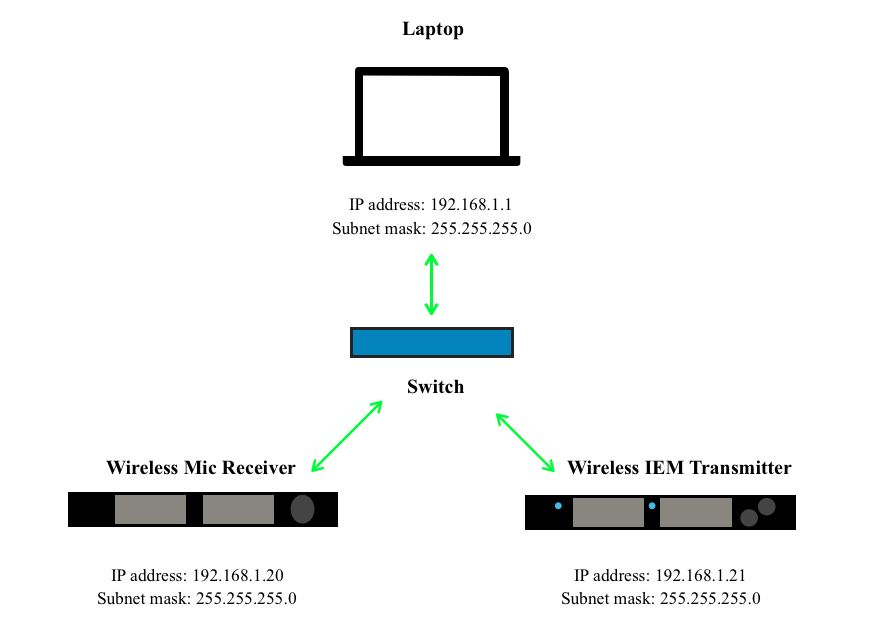
Network from Figure A with an IEM transmitter added, all talking via a switch
The switch connects the three devices all on the same local network of 192.168.1.XXX. You can tell that they are all local to this network because they have the subnet mask 255.255.255.0, therefore all devices are only looking to “talk” to messages on 192.168.1.XXX since only the values in the last octet are available for host IP addresses. Voilà! We have created our first LAN!
It may seem daunting at first, but understanding the binary behind the numbering in IP addresses and subnet masks are the key to understanding how devices know what other hosts are considered to be on their local network or LAN. With the help of switches and access points, we can expand this local network and with the addition of routers, we can include other networks. Using these expanding devices allows us to divide our network further into different topologies. In the next blog, this concept will be expanded further in Basic Networking For Live Sound Part 2: Dividing A Network. Stay tuned!
If you want to learn more about networking, there are some GREAT resources available to you online! Check out training from companies such as:
https://www.audinate.com/learning/training-certification
https://www.cisco.com/c/en/us/training-events/training-certifications.html
And more!
Endnotes
[2] https://www.cisco.com/c/en_ca/products/wireless/what-is-wifi.html
[4] Ibid.
[6] https://tools.ietf.org/html/rfc1918
[7] https://eu.dlink.com/uk/en/support/faq/firewall/what-is-dhcp-and-what-does-it-do
Resources:
Audinate. (n.d.). Dante Certification Program. https://www.audinate.com/learning/training-certification/dante-certification-program
Audio Technica U.S., Inc. (2014, November 5). Networking Fundamentals for Dante. https://www.audio-technica.com/cms/resource_library/files/89301711029b9788/networking_fundamentals_for_dante.pdf
Cisco. (n.d.) How Does a Router Work? https://www.cisco.com/c/en/us/solutions/small-business/resource-center/networking/how-does-a-router-work.html
Cisco. (2006). Networking Fundamentals. In SMB University: Selling Cisco SMB Foundation Solutions. Retrieved from https://www.cisco.com/c/dam/global/fi_fi/assets/docs/SMB_University_120307_Networking_Fundamentals.pdf
Cisco. (n.d.) What Is Wi-Fi? https://www.cisco.com/c/en_ca/products/wireless/what-is-wifi.html
D-Link. (2012-2018). What is DHCP and what does it do? https://eu.dlink.com/uk/en/support/faq/firewall/what-is-dhcp-and-what-does-it-do
Encyclopedia Brittanica. (n.d.). TCP/IP Internet Protocols. In Encyclopedia Brittanica. Retrieved April 26, 2020, from https://www.britannica.com/technology/domain-name
Generate Random MAC Addresses. (2020). Browserling. https://www.browserling.com/tools/random-mac
Internet Assigned Numbers Authority. (2020, April 21). In Wikipedia. https://en.wikipedia.org/wiki/Internet_Assigned_Numbers_Authority
Internet Engineering Task Force. (1996). Address Allocation for Private Internets (RFC 1918). Retrieved from https://tools.ietf.org/html/rfc1918
Microsoft Support. (2019, December 19). Understanding TCP/IP addressing and subnetting basics. https://support.microsoft.com/en-ca/help/164015/understanding-tcp-ip-addressing-and-subnetting-basics
Thomas, Jajish. (n.d.).What are Routing and Switching | Difference between Routing and Switching. OmniSecu.com. https://www.omnisecu.com/cisco-certified-network-associate-ccna/what-are-routing-and-switching.php